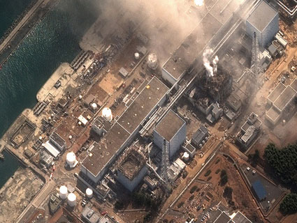
Workers in Japan are still pouring seawater on overheating nuclear reactor rods at the Fukushima Daiichi Nuclear Power Station in an effort to decrease the risk of further meltdowns. (Read Mother Jones‘ detailed and regularly updated explainer on the current situation.) Here’s what they’re up against, as Kate Sheppard and Josh Harkinson explained shortly after the emergency began:
There are six boiling-water reactors on the site, though only three were in operation at the time of the earthquake. These systems, designed by General Electric, rely on an influx of water to cool the reactor core. But the water systems require electricity that was cut off by the earthquake. It also appears that something—the initial quake, the tsunami, or aftershocks—knocked the site’s back-up generators offline. Without the cooling system bringing in water, the core of a reactor will start to overheat—which in turn heats up the water already in the system and causes more of it to turn to steam. Emergency responders have been forced to vent some of the steam, releasing radiation, in order to prevent the containment domes from exploding. They are in a race against the clock to bring in new water supplies before the reacting nuclear fuel heats up beyond control.
When I couldn’t find a schematic that showed the Fukushima reactors’ failed cooling systems in relation to their various other workings, I set out to remedy the problem in a visually accessible way. Think of the schematic diagram below like a New York City subway map. It shows the various components, connections, and relationships between the emergency water systems inside the Fukushima’s five GE Mark I reactors. (A sixth reactor is a similar, though slightly newer, design.) It is based on the Nuclear Regulatory Commission’s Boiling Water Reactor Systems Manual, which contains drawings of the various Mark I emergency systems. In places where the manual was unclear, I consulted Japanese news broadcasts. The drawings are not to scale and the layout of the pipes entirely my own (their location in relation to the various containment walls is based on the NRC manual).
Click here for an animated version of the diagram.
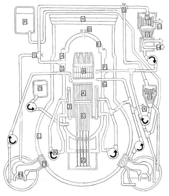 Mark I Reactor Components: (A) Uranium fuel rods; (B) Steam separator and dryer assemblies (C) Graphite control rods; (D) Vent and head spray; (E) Reactor vessel; (F) Feedwater inlet; (G) Low pressure coolant injection inlet; (H) Steam outlet; (I) Core spray inlet; (J) Jet pump; (K) Recirculation pump; (L) Concrete shell “drywell”; (M) Venting system; (N) Suppression pool; (O) Boron tank; (P) Condensate storage tank; (Q) High pressure coolant injection system; (R) HCIS turbine; (S) Automatic depressurization system; (T) Main turbine; (U) Connection to generator; (V) Condenser; (W) Circulating water; (X) Connection to outside service water; (Y) Concrete shield plug; (Z) Control rod drives. Illustrations by Joe Kloc.
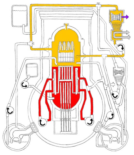 Mark I Reactor Running Normally: Recirculation loops (RED) keep pressurized water circulating through the uranium core of the reactor. When water is heated by the uranium core it turns to steam. It passes through the steam separator and dryer assemblies positioned above the core (ORANGE) and then moves through the steam pipe. The steam is used to turn a turbine connected (PURPLE) to an electrical generator. It is then turned back into liquid by a condenser and cooled by a pipe (GREY) of circulating cold water. The water is then pumped back into the reactor, where the process begins again.
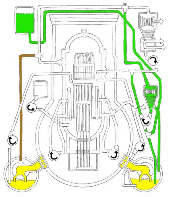 Mark I Reactor High Pressure Emergency Core Cooling System: The Automatic Depressurization System (BROWN) can be used to release pressure in the reactor. It reroutes some of the steam to the suppression chamber. The High Pressure Coolant Injection System (GREEN) takes steam from the steam pipe and converts it into water that is then pumped back into the reactor to keep the core cool. Pressure can also be released directly (YELLOW) into the suppression chamber.
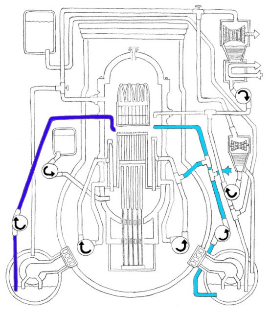 Mark I Reactor Low Pressure Emergency Core Cooling System: The Core Spray System (DARK BLUE) takes water from the suppression chamber and sprays it onto the core. The Low Pressure Coolant Injection System (LIGHT BLUE) takes outside water as well as water from the supression chamber and pumps some into the recirculation system (shown as RED in first diagram) and sprays the rest on the core.
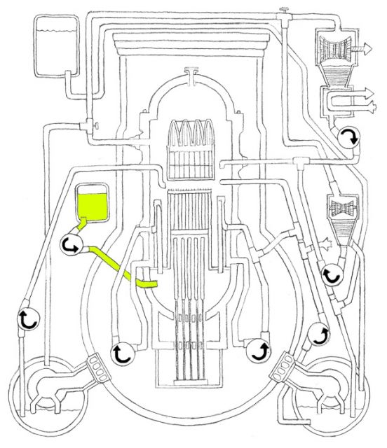 Mark I Reactor Standby Liquid Control System: Most of the Fukushima reactors are powered by low enriched uranium. When the LEU is hit with neutrons, the atoms split, releasing energy (which heats the water) and more neutrons. Because boron (LIME) absorbs neutrons, injecting it into the core can help shut down the reactor.
